![]()
Sparen's Danmakufu ph3 Tutorials Lesson 30 - Introduction to 3D Sprites and 3D Backgrounds
Table of Contents
- Part 1: What will be covered in this lesson?
- Part 2: What are 3D Sprites?
- Part 3: How do I use 3D Sprites in Danmakufu?
- Part 4: How do the 3D Coordinate System and Camera work?
- Part 5: How do I create static 3D Backgrounds?
- Part 6: How do yaw, pitch, and roll work in Danmakufu?
- Part 7: How do I create scrolling 3D Backgrounds?
- Part 8: How do I utilize fog?
- Summary
- Sources and External Resources
Part 1: What will be covered in this lesson?
In this lesson, we will cover 3D Sprites and basic 3D backgrounds in Danmakufu ph3. It is expected that you are already familiar with 2D sprites and backgrounds. If you are not familiar with these, refer to Lesson 13 and Lesson 22.
This lesson will go into depth with regards to camera functionality and will cover other miscellaneous topics with regards to 3D in Danmakufu ph3. Please note that 3D Camera guides are located throughout this guide and are not all located in Part 4.
Part 2: What are 3D Sprites?
We've already worked with 2D Sprites that render on the screen in a rather boring manner. You can set a Z coordinate to these but it doesn't actually do anything. 3D Sprites work similarly but you can now work with that extra coordinate.
3D Sprites have the standard Source and Dest rect functionalities but instead of having an automatic centering system such as ObjSprite2D_SetDestCenter(), they instead have ObjSprite3D_SetSourceDestRect(). This function is different in that it does center the sprite, but it centers the sprite at the origin - (0, 0, 0). And where exactly is this origin?
Part 3: How do I use 3D Sprites in Danmakufu?
For this tutorial, we will be working in a Background Script. I will attempt to have a double panel with code on one side and a screenshot on the other but in many cases it will be necessary for you, the student, to run the code samples yourself and see how things function.
Let's start by trying to render a boring 2D sprite on the screen.
task Experiment0{
    let path1 = GetCurrentScriptDirectory ~ "img/RaikoCutIn.png";

    let cameracount = 0;

    let obj1 = ObjPrim_Create(OBJ_SPRITE_2D);
    ObjRender_SetBlendType(obj1, BLEND_ALPHA);
    Obj_SetRenderPriority(obj1, 0.21);
    ObjPrim_SetTexture(obj1, path1);
    ObjSprite2D_SetSourceRect(obj1, 0, 0, 368, 460);
    ObjSprite2D_SetDestRect(obj1, -184, -230, 184, 230);
    loop{

        cameracount++;
        yield;
    }
}
As expected, the image renders and centers itself at (0, 0), the default position. Now let's convert it to a 3D sprite.
task Experiment1{
let path1 = GetCurrentScriptDirectory ~ "img/RaikoCutIn.png";
let cameracount = 0;
let obj1 = ObjPrim_Create(OBJ_SPRITE_3D);
ObjRender_SetBlendType(obj1, BLEND_ALPHA);
Obj_SetRenderPriority(obj1, 0.21);
ObjPrim_SetTexture(obj1, path1);
ObjSprite3D_SetSourceRect(obj1, 0, 0, 368, 460);
ObjSprite3D_SetDestRect(obj1, -184, -230, 184, 230);
loop{
cameracount++;
yield;
}
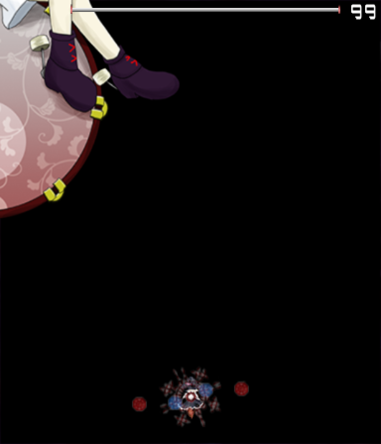
}
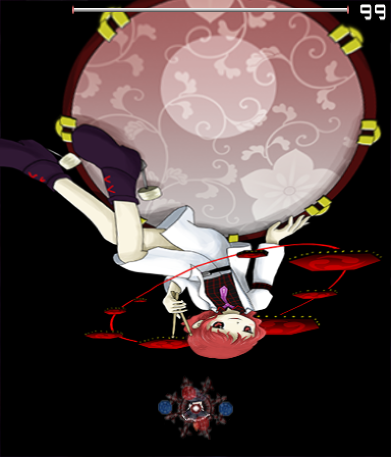
WHAT. is a pretty accurate description. ObjSprite3D_SetSourceDestRect(obj1, 0, 0, 368, 460); gives you the same result. Obviously, something strange is going on here. Let's find out what it is.
So far, we've been working with 2D sprites. Bullets, text, 2D sprites, etc. have all used a standard coordinate system - (0, 0) is in the top left of the playing field for render priorities between 0.20 and 0.80, and they increase to the right and down such that the bottom right of the playing field, (GetStgFrameWidth, GetStgFrameHeight), is (384, 448). However, the 3D coordinate system does NOT function in this same way as we have just observed, and the 3D Camera system has some other tricks up its sleeve...
Part 4: How do the 3D Coordinate System and Camera work?
Now, I can assure you that Raiko is ACTUALLY positioned at (0, 0, 0). There are just some... fun defaults we need to work with.
First, the coordinate system (assuming elevation and azimuth are set to 0, which they are not by default). Z is horizontal and Y remains vertical, while the X axis goes into the screen. Notably, (0, 0, 0) is not in the top left by any stretch - it's dead center in the playing field in all three axes.
By default, (0, 0, 0) happens to be the focal point of the camera as well. The camera itself is what controls the display. The camera has a default unchangeable position in Danmakufu and from that position always faces the Focal Point. Note that Danmakufu calls the Focal Point the Focus Point in its functions.
Next we need to describe Azimuth and Elevation angles. Let's first say that the X (depth)-Z (width) plane is the ground. The camera lying flat on the ground pointing forwards and aligned the way we see it has an elevation and azimuth of 0.
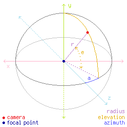
Imagine a sphere as shown above (thanks to Drake on MotK). If we rotate the camera upwards on that sphere, it will continue to point at the focal point, but since it's above the ground, it has an angle of elevation compared to where it was before. Alternatively, let's say that there's a circle drawn on the ground and the camera is on the circle. If we move the camera along the circle, the Azimuth angle changes. Like before, it still points at the focal point.
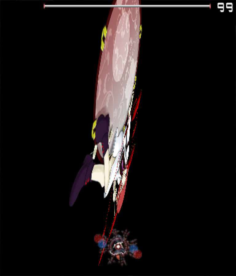
OK. So we know some more about how these angles and coordinate systems work. Why does Raiko appear like that?
Short answer: Danmakufu's default Azimuth angle is 15, and its default Elevation angle is 45.
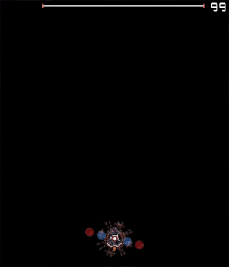
Now, we've run into a problem. Danmakufu's default Azimuth is 15. If we set it to zero, we get the following:
task Experiment2{
    let path1 = GetCurrentScriptDirectory ~ "img/RaikoCutIn.png";

    let cameracount = 0;

    SetCameraAzimuthAngle(0);

    let obj1 = ObjPrim_Create(OBJ_SPRITE_3D);
    ObjRender_SetBlendType(obj1, BLEND_ALPHA);
    Obj_SetRenderPriority(obj1, 0.21);
    ObjPrim_SetTexture(obj1, path1);
    ObjSprite3D_SetSourceRect(obj1, 0, 0, 368, 460);
    ObjSprite3D_SetDestRect(obj1, -184, -230, 184, 230);
    loop{

        cameracount++;
        yield;
    }
}
Intuitively, this makes sense. If the azimuth is zero, then we're looking straight at the 3D sprite, which is flat, from the side. The rects we provided rendered the image in the X-Y plane, where X is depth and Y is height. There's no Z (width) component. And therefore, it's basically invisible. Therefore, let's instead try setting Azimuth to 90, which is a common standard for many stage backgrounds (the alternative is -90, which we will discuss later). Do note that this means the default axis we are looking down will change.
task Experiment3{
    let path1 = GetCurrentScriptDirectory ~ "img/RaikoCutIn.png";

    let cameracount = 0;

    SetCameraAzimuthAngle(90);

    let obj1 = ObjPrim_Create(OBJ_SPRITE_3D);
    ObjRender_SetBlendType(obj1, BLEND_ALPHA);
    Obj_SetRenderPriority(obj1, 0.21);
    ObjPrim_SetTexture(obj1, path1);
    ObjSprite3D_SetSourceRect(obj1, 0, 0, 368, 460);
    ObjSprite3D_SetDestRect(obj1, -184, -230, 184, 230);
    loop{

        cameracount++;
        yield;
    }
}
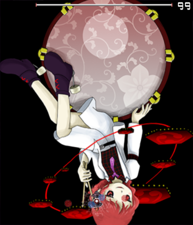
OK. She's fixed in one angle. Positive azimuth moves the camera to the right, while negative azimuth moves the camera to the left. Now let's set elevation to 0.
task Experiment4{
    let path1 = GetCurrentScriptDirectory ~ "img/RaikoCutIn.png";

    let cameracount = 0;

    SetCameraAzimuthAngle(90);
    SetCameraElevationAngle(0);

    let obj1 = ObjPrim_Create(OBJ_SPRITE_3D);
    ObjRender_SetBlendType(obj1, BLEND_ALPHA);
    Obj_SetRenderPriority(obj1, 0.21);
    ObjPrim_SetTexture(obj1, path1);
    ObjSprite3D_SetSourceRect(obj1, 0, 0, 368, 460);
    ObjSprite3D_SetDestRect(obj1, -184, -230, 184, 230);
    loop{

        cameracount++;
        yield;
    }
}
So now things seem to be OK, if you ignore the fact that she's rotated 180 degrees.
task LearningElevationAzimuth{
    let path1 = GetCurrentScriptDirectory ~ "img/RaikoCutIn.png";

    let cameracount = 0;

    let obj1 = ObjPrim_Create(OBJ_SPRITE_3D);
    ObjRender_SetBlendType(obj1, BLEND_ALPHA);
    Obj_SetRenderPriority(obj1, 0.21);
    ObjPrim_SetTexture(obj1, path1);
    ObjSprite3D_SetSourceRect(obj1, 0, 0, 368, 460);
    ObjSprite3D_SetDestRect(obj1, -184, -230, 184, 230);

    let obj2 = ObjText_Create();
    ObjRender_SetPosition(obj2, 32, 32, 1);
    loop{

        SetCameraAzimuthAngle(GetPlayerX - GetStgFrameWidth()/2);
        SetCameraElevationAngle(GetStgFrameHeight()/2 - GetPlayerY);

        ObjText_SetText(obj2, "Azimuth: " ~ ToString(GetPlayerX - GetStgFrameWidth()/2) ~ "[r]" ~ "Elevation: " ~ ToString(GetStgFrameHeight()/2 - GetPlayerY));

        cameracount++;
        yield;
    }
}
Try out the above code. Especially try out setting one of the angles to 0 or 90 and varying the other exclusively. The player's position will determine the Elevation and Azimuth angles for the camera. Note that it's simply impossible to get Raiko into her standard 2D sprite positioning using this example.
OK, OK. Your head probably hurts now. Let's flip her right side up... err, which axis do we rotate around?
task Learning3DSpriteAngleXY{
    let path1 = GetCurrentScriptDirectory ~ "img/RaikoCutIn.png";

    let cameracount = 0;

    SetCameraAzimuthAngle(90);
    SetCameraElevationAngle(0);

    let obj1 = ObjPrim_Create(OBJ_SPRITE_3D);
    ObjRender_SetBlendType(obj1, BLEND_ALPHA);
    Obj_SetRenderPriority(obj1, 0.21);
    ObjPrim_SetTexture(obj1, path1);
    ObjSprite3D_SetSourceRect(obj1, 0, 0, 368, 460);
    ObjSprite3D_SetDestRect(obj1, -184, -230, 184, 230);

    let obj2 = ObjText_Create();
    ObjRender_SetPosition(obj2, 32, 32, 1);
    loop{

        ObjRender_SetAngleX(obj1, GetPlayerX - GetStgFrameWidth()/2);
        ObjRender_SetAngleY(obj1, GetStgFrameHeight()/2 - GetPlayerY);

        ObjText_SetText(obj2, "X Angle: " ~ ToString(GetPlayerX - GetStgFrameWidth()/2) ~ "[r]" ~ "Y Angle: " ~ ToString(GetStgFrameHeight()/2 - GetPlayerY));

        cameracount++;
        yield;
    }
}
In this example, if you move up, Raiko rotates about the y axis (vertical). Perhaps counter-intuitively, this makes her spin like a sign attached to a stick. And indeed, that's a great way to think about this. Think about holding a flat sign vertically. The vertical axis (the y axis) is aligned along the thing you hold - the stick? Pole? Whatever its called. All that matters is that when you rotate the sign/flip it to show the other side, you're rotating about the y axis.
But what happened to the x axis? It's as if Raiko is flipping into the ground.
Recall the configuration where elevation and azimuth were set to 0. The x axis represents depth in that view. However, we've set Azimuth to 90, meaning we're now looking at that view from a different angle. In fact, it's as if the x and z axes have switched places.
There are other configurations that we can try out for elevation and azimuth, but setting azimuth into a space we are familiar with is most important.
For the remainder of this tutorial and in all future tutorials referencing 3D backgrounds, we will utilize an Azimuth angle of -90 in order to maintain the x axis being horizontal, the y axis being vertical, and the z axis being the depth axis. Using -90 for Azimuth instead of 90 means that the X axis will increase as we move to the right and decrease as we move to the left like with 2D sprites. The y direction will not behave the same way as with 2D sprites, but since increasing the y coordinate increases the height, it shouldn't be too much of a stretch given that we're thinking in 3D. The following example should feel like you're working with 2D sprites if you ignore the y coordinate being opposite.
task Learning3DSpriteDirXY{
    let path1 = GetCurrentScriptDirectory ~ "img/RaikoCutIn.png";

    let cameracount = 0;

    SetCameraAzimuthAngle(-90);
    SetCameraElevationAngle(0);

    let obj1 = ObjPrim_Create(OBJ_SPRITE_3D);
    ObjRender_SetBlendType(obj1, BLEND_ALPHA);
    Obj_SetRenderPriority(obj1, 0.21);
    ObjPrim_SetTexture(obj1, path1);
    ObjSprite3D_SetSourceRect(obj1, 0, 0, 368, 460);
    ObjSprite3D_SetDestRect(obj1, -184, -230, 184, 230);
    ObjRender_SetAngleX(obj1, 180); // Flip

    let obj2 = ObjText_Create();
    ObjRender_SetPosition(obj2, 32, 32, 1);
    loop{

        ObjRender_SetX(obj1, GetStgFrameWidth()/2 - GetPlayerX);
        ObjRender_SetY(obj1, GetStgFrameHeight()/2 - GetPlayerY);

        ObjText_SetText(obj2, "X: " ~ ToString(ObjRender_GetX(obj1)) ~ "[r]" ~ "Y: " ~ ToString(ObjRender_GetY(obj1)));

        cameracount++;
        yield;
    }
}
Part 5: How do I create static 3D Backgrounds?
Congratulations on getting through all of that stuff above. We've exited the introduction to the coordinate system and camera without discussing Yaw/Pitch/Roll, but those can wait a little while since they involve manipulating the actual camera rather than the camera's relation to the scene. For now, we'll do a simple 3D background comprised of 3D sprites, and will discuss camera radius and perspective clipping.
For now, let's imagine a scene. Think of a location - maybe a small village, or a building, etc. Now imaging you're flying in the air with a camera. Your camera is pointing straight at a location in the village. The distance between your camera and that point is the camera radius, which in Danmakufu defaults to 500 pixels. For convenience's sake, the camera can't really capture anything *too* far away, say over the horizon. So that stuff, as well as stuff too close to the camera, aren't captured. That's the perspective clip - the parts of the scene in the direction the camera is facing where it just can't capture.
Now, back to the scene. You can fly around it and the only restriction (for now) is that the camera must face a single point in the scene. Where are the objects relative to one another? How high are they? Those are the kinds of things to think about when designing a 3D stage background. Typically you'd have a never-ending path with trees or the like, but for now we'll have a simple background that behaves more like the set of a play - you have cardboard or otherwise static objects placed in the scene and you look at it from a single angle.
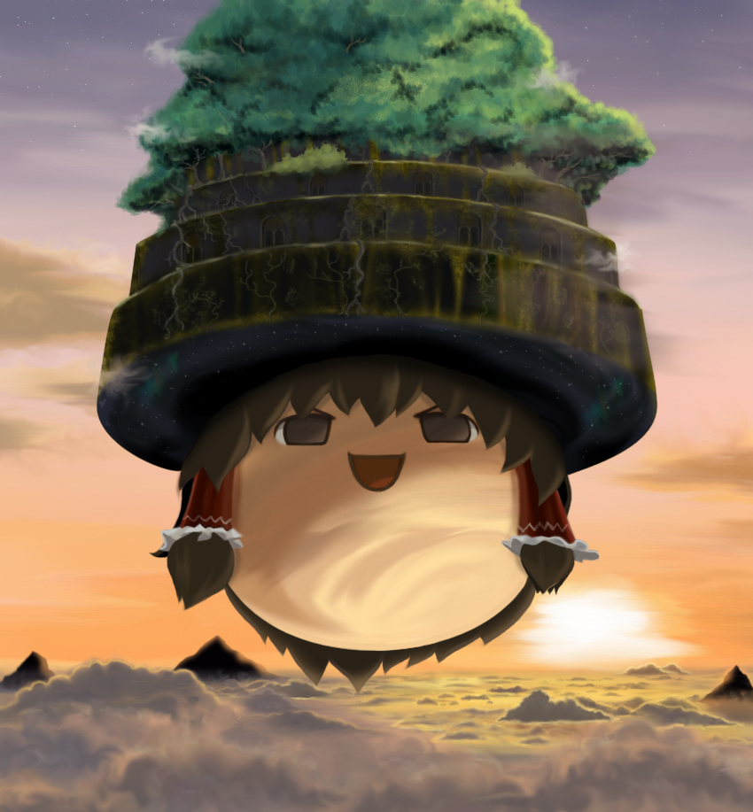
Of course to lighten the mood our example will be a Yukkuri village with bouncing Yukkuris. We'll have a closed area made with 3D sprites, and will rotate the camera around while Yukkuri bounce at us. What fun!
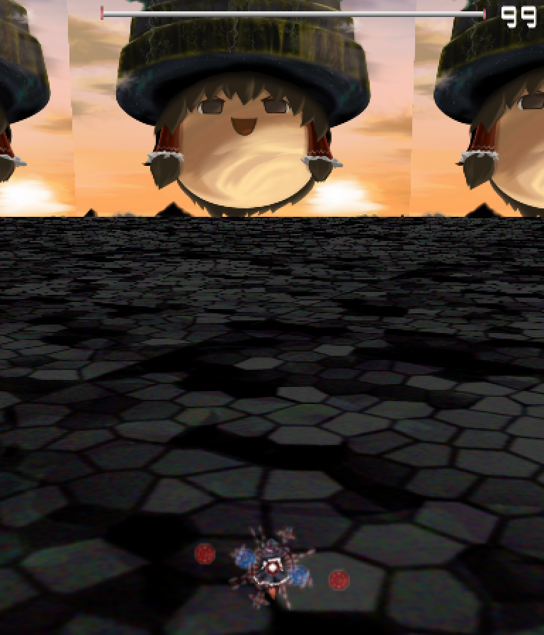
Let's start with the floor. I'm using this image for flooring, with the following code to start. Please note that all of the images used in this example demo are intended to be placeholders and are only being used to highlight the code. It is recommended to utilize your own graphical assets in your own projects.
task MainBG{
    let path1 = GetCurrentScriptDirectory ~ "img/spcdbkgd3.png";

    let cameracount = 0;

    SetCameraAzimuthAngle(-90);
    SetCameraElevationAngle(10);

    let obj1 = ObjPrim_Create(OBJ_SPRITE_3D); // Flooring
    ObjRender_SetBlendType(obj1, BLEND_ALPHA);
    Obj_SetRenderPriority(obj1, 0.21);
    ObjPrim_SetTexture(obj1, path1);
    ObjSprite3D_SetSourceDestRect(obj1, 0, 0, 512*32, 512*32);
    ObjRender_SetAngleX(obj1, 90);

    loop{
        SetCameraAzimuthAngle(-90 + cameracount/8);
        cameracount++;
        yield;
    }
}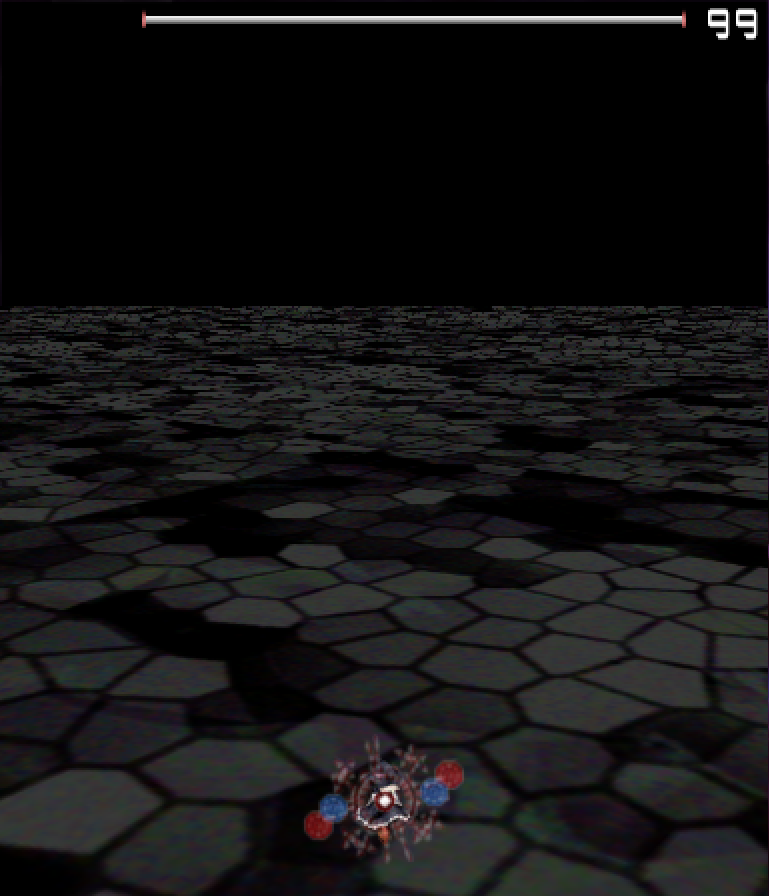
Note that we've changed the Elevation Angle. We don't want the camera to be looking straight along the ground - we want to simulate someone above ground. And so we have an elevation angle. I've also set the source and dest rect to a rather large number. This is because you want the image to cover a large space. Typically this much is overkill, however. I've also rotated the 3D sprite 90 degrees about the X axis such that it's the floor and not a wall. Finally, in the loop I've set the Azimuth Angle to change over time - gradually as to not make the viewer feel motion sickness.
Next, let's add some background to replace the boring black background and add some color. I'm using this image.
task MainBG{
    let path1 = GetCurrentScriptDirectory ~ "img/u3l30sample1.png";
    let path2 = GetCurrentScriptDirectory ~ "img/u3l30sample2.jpg";

    let cameracount = 0;

    SetCameraAzimuthAngle(-90);
    SetCameraElevationAngle(10);

    ascent(i in 0..12) {
        let distance = 1480;
        let objHouse = ObjPrim_Create(OBJ_SPRITE_3D); // Background
        ObjRender_SetBlendType(objHouse, BLEND_ALPHA);
        Obj_SetRenderPriority(objHouse, 0.21);
        ObjPrim_SetTexture(objHouse, path2);
        ObjSprite3D_SetSourceDestRect(objHouse, 0, 0, 850, 917);
        ObjRender_SetAngleY(objHouse, 360/12*i);
        ObjRender_SetAngleX(objHouse, 180);
        ObjRender_SetPosition(objHouse, distance*cos(90 - 360/12*i), 300, distance*sin(90 - 360/12*i));
    }

    let obj1 = ObjPrim_Create(OBJ_SPRITE_3D); // Flooring
    ObjRender_SetBlendType(obj1, BLEND_ALPHA);
    Obj_SetRenderPriority(obj1, 0.21);
    ObjPrim_SetTexture(obj1, path1);
    ObjSprite3D_SetSourceDestRect(obj1, 0, 0, 413*32, 407*32);
    ObjRender_SetAngleX(obj1, 90);

    loop{
        SetCameraAzimuthAngle(-90 + cameracount/8);
        cameracount++;
        yield;
    }
}
The main thing to note here is render order. As mentioned in prior guides, within the same render priority the things spawned later render over the things spawned before. In addition, when calculating the position, I incorporate a 90 into the angle in order to ensure that they all face the center. This is actually a very hackish solution that takes advantage of the ring nature of images - without the 90 degree shift, the Y rotation of the individual sprites all face away from the center. However, by keeping the angles they are at but moving them a quarter of the way around the circle, all of the sprites become perpendicular to the lines from the camera focus to them. In the diagram below, each colored line in the example without shifting becomes the same colored line in the example with the 90 degree clockwise shift.
Do note that the positioning of the background panels was done haphazardly and so some of the panels may intersect with others and render over those improperly due to render order.
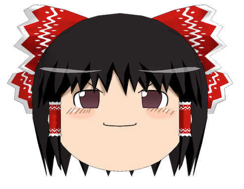
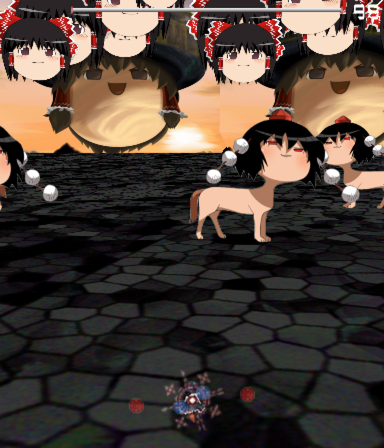
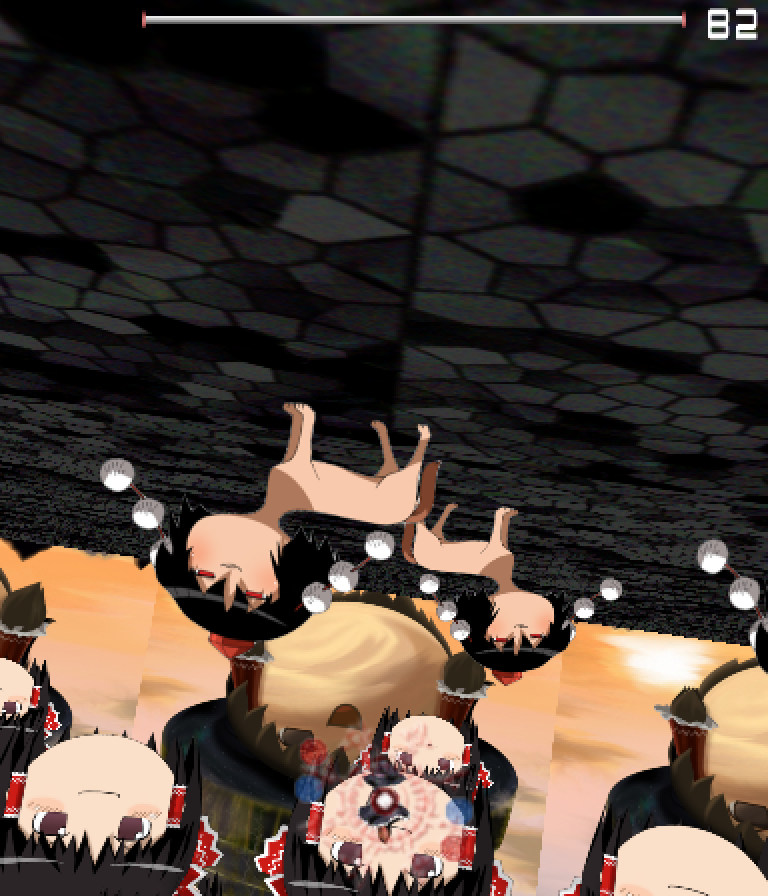
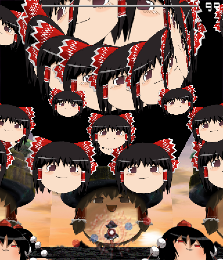
Now let's add some extras in the scene. Since the camera stays in the same position, I'm only going to put up the front side of these, like the play example mentioned earlier. No point in including the walls of the houses if the camera never has a chance to see them! For now, I'll consider Aya to be a mobile building given that she can be quite persistent as she watches over your shoulder trying to extract a scoop from you. Aya.
task MainBG{
    ...

    ascent(i in 0..6) {
        let distance1 = 512;
        let distance2 = 1024;
        CreateAyaA1(distance1, i, 1, 0.22); // Forcibly render closer ones higher
        CreateAyaA1(distance2, i, -1, 0.21);
    }

    loop{
        SetCameraAzimuthAngle(-90 + cameracount/8);
        cameracount++;
        yield;
    }
}

task CreateAyaA1(dist, ID, dir, rp) {
    let objcount = 0;
    let pathAya = GetCurrentScriptDirectory ~ "img/u3l30sample3.png";
    let objAya = ObjPrim_Create(OBJ_SPRITE_3D); // Aya
    ObjRender_SetBlendType(objAya, BLEND_ALPHA);
    Obj_SetRenderPriority(objAya, rp);
    ObjPrim_SetTexture(objAya, pathAya);
    ObjSprite3D_SetSourceDestRect(objAya, 0, 0, 320, 250);
    ObjRender_SetAngleX(objAya, 180);
    loop {
        ObjRender_SetAngleY(objAya, 360/6*ID + dir*objcount + 90 + 90*dir); // Offset + change over time + reflections to face direction
        ObjRender_SetPosition(objAya, dist*cos(90 - 360/6*ID - objcount*dir), 0, dist*sin(90 - 360/6*ID - objcount*dir)); // Base + Offset + change over time
        objcount += 1/6;
        yield;
    }
}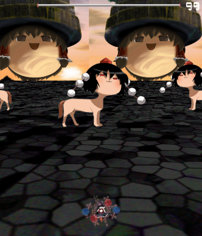
Here we need to do some work to allow for the Aya army to move while maintaining the intended angle. However, it's not something that can't be done with some angle offsets. We maintain the 90 degree offset and the primary base angle, but the angle of the Ayas needs to change over time, so we have to set the Y angle as well. In this case, if the Ayas rotate clockwise by subtracting objcount*dir, we add the objcount*dir to the Y rotation in order to cancel out the effect. The 90 + 90*dir is only used to flip the sprites for the Ayas moving in the other direction.
As a final component to this static stage, we'll add some bouncing Yukkuris.
task MainBG{
    ...

    loop{
        SetCameraAzimuthAngle(-90 + cameracount/8);

        if (cameracount % 72 == 0) {
            ascent(i in 0..12) {
                CreateYukkuriA1(i, cameracount);
            }
        }

        cameracount++;
        yield;
    }
}

task CreateYukkuriA1(ID, offset) {
    let objcount = 0;
    let dist = 1520;
    let pathYuk = GetCurrentScriptDirectory ~ "img/u3l30sample4.png";
    let objYuk = ObjPrim_Create(OBJ_SPRITE_3D); // Yukkuri
    ObjRender_SetBlendType(objYuk, BLEND_ALPHA);
    Obj_SetRenderPriority(objYuk, 0.21);
    ObjPrim_SetTexture(objYuk, pathYuk);
    ObjSprite3D_SetSourceRect(objYuk, 0, 0, 494, 384);
    ObjSprite3D_SetDestRect(objYuk, -494/4, -384/4, 494/4, 384/4);
    ObjRender_SetAngleX(objYuk, 180);
    ObjRender_SetZTest(objYuk, true);
    loop {
        if (dist < -1520) {
            Obj_Delete(objYuk);
        }
        ObjRender_SetAngleY(objYuk, 360/12*ID - offset);
        ObjRender_SetPosition(objYuk, dist*cos(90 - 360/12*ID + offset), 540 + 270*cos(objcount*6), dist*sin(90 - 360/12*ID + offset));
        objcount += 1;
        dist -= 5;
        yield;
    }
}
Here we use a distance based system where the objects spawn at a given distance and last for a certain distance before deleting. This technique is commonly used in endlessly scrolling backgrounds to delete sprites that have moved past the camera's range - something we will take a look at in the next section. I have also set the Y coordinate to oscillate over time using a sine wave (well, cosine in this case).
Finally, to see what our setup looks from afar (the 'floating camera') view...
task MainBG{
    let path1 = GetCurrentScriptDirectory ~ "img/u3l30sample1.png";
    let path2 = GetCurrentScriptDirectory ~ "img/u3l30sample2.jpg";

    let cameracount = 0;

    SetCameraAzimuthAngle(-90);
    SetCameraElevationAngle(10);
    SetCameraPerspectiveClip(0, 50000);
    SetCameraRadius(8000);

    ...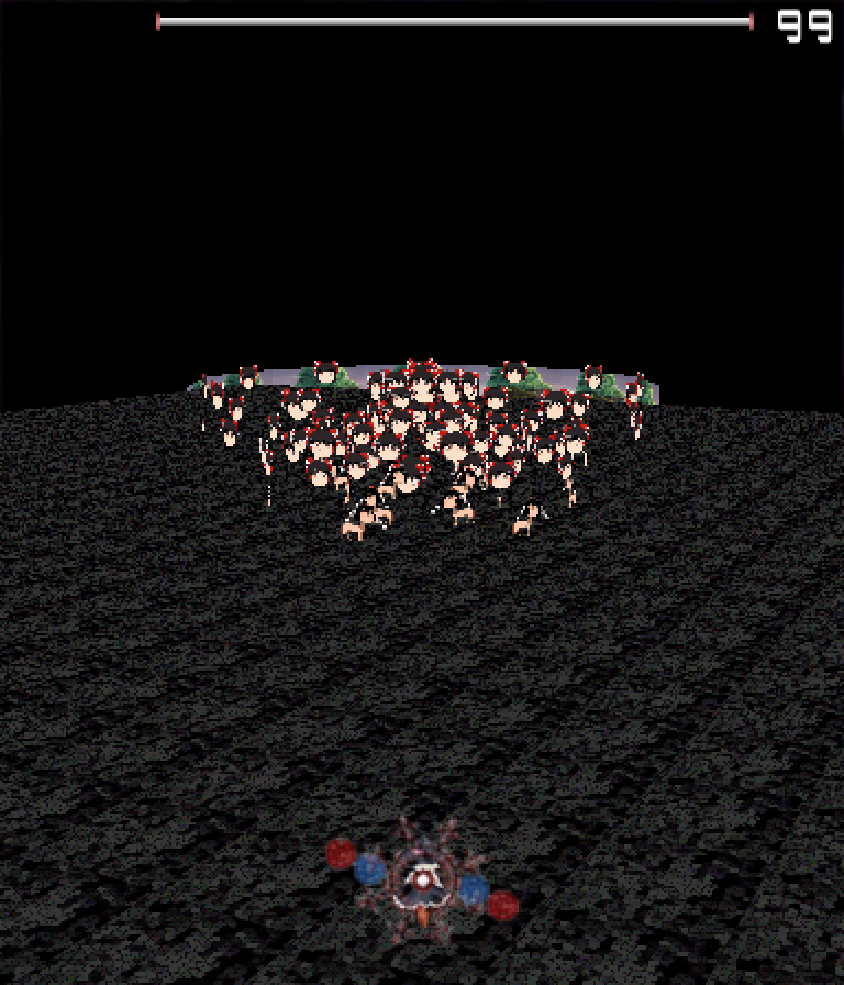
There are a few things to note here. First, the 'background' and floor were on the same render priority layer. As a result, the floor covers most of the former background from this distance and angle. When designing stages in 3D, it is important to keep this in mind as you determine what components are shown to the player and which components are cleverly hidden. In addition, various components may interact in unwanted ways - for example, you may want certain different types of object to render behind one another in a very specific way - these concepts require careful thought and consideration when designing the background from a code perspective.
In addition, we utilize two new functions here, one of which sets the radius of the camera (the distance between the focal point of the camera and the camera itself) and one which sets the perspective clip. The default max perspective clip is something you will probably want to override when manipulating the camera radius, but again, careful tuning can allow you to cover up some unwanted components while showing the parts you do want.
Part 6: How do yaw, pitch, and roll work in Danmakufu?
The last thing we will do with the Yukkuri example is cover yaw, pitch, and roll. Before we covered setting the camera focus and the elevation/azimuth, which changes the camera's location within the scene. Now we'll cover manipulating the camera itself.
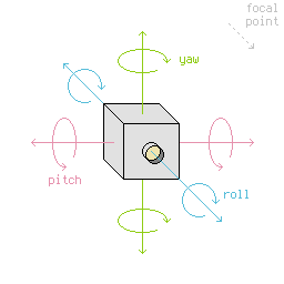
Let's cover these one by one. First, yaw. Let's say that the camera is attached to the top of a vertical pole, facing to the side. Rotating the pole rotates the camera, giving you a 360 degree view of the landscape. This rotation parallel to the ground is a change in yaw and is great for panoramic views.
A good way to try out yaw is to change the camera yaw instead of changing the azimuth over time.
    ...

    loop{
        SetCameraYaw(-90 + cameracount/8);

        if (cameracount % 72 == 0) {
            ascent(i in 0..12) {
                CreateYukkuriA1(i, cameracount);
            }
        }

        cameracount++;
        yield;
    }

    ...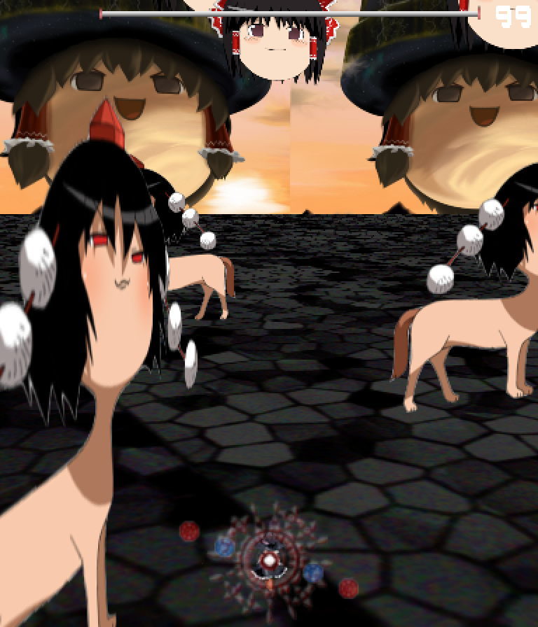
Note how close the Ayas are. We created the Ayas at a distance of 512. However, keep the camera's radius in mind. Before, the camera was rotating AROUND the focus at a distance of 500, but now the camera isn't pointing at the camera focus - it's keeping its position and rotating around its own axis, so it ends up staring the Ayas straight in the face. And indeed, when the camera turns to face the Ayas that were previously just 12 units behind the camera, the Ayas are very close.
See the animation below.
Danmakanvas is a Javascript Danmaku simulation made by Sparen. It does NOT work the same way as Danmakufu. Please be advised that the speed at which the simulation runs is therefore not equivalent to the speed that the code would run in Danmakufu.
In the above animation, the red bullets are the Ayas, while the blue bullet is the camera. The small green bullets show the direction the camera is facing. The white bullet in the center denotes the focus. Note that the location of the camera is not the same as in DNH, but the example should still be relevant. Bullet trails note the previous positions. Note how the visible arc for changing Azimuth differs from that of changing Yaw.
Besides Yaw, there are also Pitch and Roll. For Roll, the easiest way to imagine it is to use the standard airplane example - if the airplane rotates around its primary axis, that's roll. Now just imagine the airplane as a camera.
Alternatively, imagine attaching a camera to Umaru's head in the above gif. As she rolls, so does the camera.
Roll is typically useful in tubular and symmetric backgrounds. In other cases, it's more likely to make the people playing your game want to vomit, so please use carefully. However, please note that this extends to Pitch as well. Depending on your Azimuth angle, Roll and Pitch may have their effects swapped, similar to how the horizontal axis changed back when we were working with Raiko earlier in this tutorial. In general, Pitch will rotate the camera towards the ground, then back up towards the sky.
    ...

    loop{
        SetCameraRoll(-90 + cameracount/8);

        if (cameracount % 72 == 0) {
            ascent(i in 0..12) {
                CreateYukkuriA1(i, cameracount);
            }
        }

        cameracount++;
        yield;
    }

    ...
    ...

    loop{
        SetCameraPitch(-90 + cameracount/8);

        if (cameracount % 72 == 0) {
            ascent(i in 0..12) {
                CreateYukkuriA1(i, cameracount);
            }
        }

        cameracount++;
        yield;
    }

    ...
As usual, there's no better teacher than experience, so try the above substitutions and feel free to experiment with the scene.
That's all for the Yukkuris. Now back to a more serious example.
Part 7: How do I create scrolling 3D Backgrounds?
To close off this guide we will cover scrolling 3D backgrounds and fog. Here we will build the kind of background script that you will actually be able to use, and will therefore work off of the default background script. In addition, we will be utilizing free graphics from the Pixar 128 texture library, which provides a large number of beautiful 1024x1024 graphics. For this tutorial, I will only assume that you have converted these to a jpg from a tif.
Let's start by copying over the default Danmakufu Ice Mountain background and removing the Ice Mountain from it. Note that I have also set the Azimuth to -90 and am no longer setting the camera focus, camera radius, and fog - fog will not be used in this example, while the others are not needed at the moment.
let bSpell = false;

@Initialize {
    SetCameraElevationAngle(35);
    SetCameraAzimuthAngle(-90);

    TNormalBackground();
    TSpellBackground();
}

@MainLoop {
    let objScene = GetEnemyBossSceneObjectID();
    if(objScene != ID_INVALID && ObjEnemyBossScene_GetInfo(objScene, INFO_IS_SPELL)) {
        bSpell = true;
    } else {
        bSpell = false;
    }

    yield;
}


task TNormalBackground() {
    let frameInvisible = 0;
    let cameracount = 0;
    loop {
        if(bSpell) {
            frameInvisible++;
            if(frameInvisible >= 60) {
                //Obj_SetVisible(obj, false);
            }
        } else {
            frameInvisible = 0;
            //Obj_SetVisible(obj, true);
        }

        cameracount++;
        yield;
    }
}

task TSpellBackground {
    let alpha = 0;
    let frame = 0;
    loop {
        if(bSpell) {
            alpha += 4;
        } else {
            alpha = 0;
        }

        frame++;
        yield;
    }

}
For this guide we will only fill out TNormalBackground, as this is the stage background. Spell backgrounds are typically generated by standard 2D sprites and are not the focus of this guide.
Now, a 3D scrolling stage background. We will want some kind of ground, maybe some trees or the like, and a background at the far end. Remember the play analogy from before - there's a set of static objects, and the camera is looking at the set.
Let's begin with the flooring. We'll lay down some flooring and scroll it. How to scroll it? Recall Lesson 22. We'll use the same strategy here. For this part I will use a large flat background in conjunction with another texture for a path in the center. I'm using the Dirt and Gravel, and Lawn Grass textures for this guide. Note that I've set the Elevation Angle to 30 elsewhere for the image.
task TNormalBackground() {
    let frameInvisible = 0;
    let cameracount = 0;
    let scrollspeed = 8;

    let path1 = GetCurrentScriptDirectory ~ "img/u3l30sampleB1.png";
    let path2 = GetCurrentScriptDirectory ~ "img/u3l30sampleB2.png";

    let obj1 = ObjPrim_Create(OBJ_SPRITE_3D); // Flooring
    ObjRender_SetBlendType(obj1, BLEND_ALPHA);
    Obj_SetRenderPriority(obj1, 0.21);
    ObjPrim_SetTexture(obj1, path1);
    ObjSprite3D_SetDestRect(obj1, -1024, -1024 * 2, 1024, 1024 * 2); // Output ratio is 1x2
    ObjRender_SetAngleX(obj1, 90);

    let obj2 = ObjPrim_Create(OBJ_SPRITE_3D); // Path
    ObjRender_SetBlendType(obj2, BLEND_ALPHA);
    Obj_SetRenderPriority(obj2, 0.21);
    ObjPrim_SetTexture(obj2, path2);
    ObjSprite3D_SetDestRect(obj2, -128, -1024 * 2, 128, 1024 * 2); // Output ratio is 1x16
    ObjRender_SetAngleX(obj2, 90);

    loop {
        if(bSpell) {
            frameInvisible++;
            if(frameInvisible >= 60) {
                Obj_SetVisible(obj1, false);
                Obj_SetVisible(obj2, false);
            }
        } else {
            frameInvisible = 0;
            Obj_SetVisible(obj1, true);
            Obj_SetVisible(obj2, true);
        }

        // Scroll by setting the source rects
        ObjSprite3D_SetSourceRect(obj1, 0, 0 + cameracount*scrollspeed, 1024*8, 1024 * 16 + cameracount*scrollspeed);
        ObjSprite3D_SetSourceRect(obj2, 0, 0 + cameracount*scrollspeed, 1024  , 1024 * 16 + cameracount*scrollspeed);

        cameracount++;
        yield;
    }
}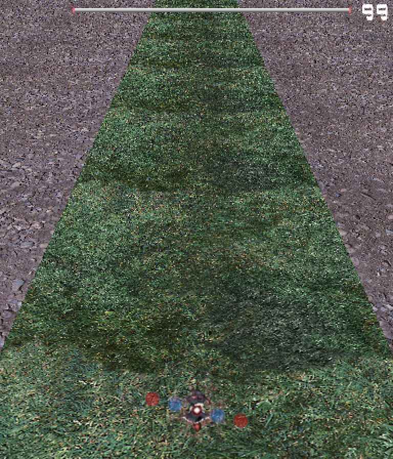
There are some things to note. First, the elevation angle makes a big difference in how much of the background is visible. You could do with a birds-eye view and not need a static background on the horizon, or you could look forwards, requiring something in the background. In addition, the dest rect controls where the background renders, while the source rect controls scale. Feel free to scale up or scale down your graphics by using the tiling. And here's the key part - tiling. You will want seamless textures for these kinds of backgrounds - textures where if you were to tile the graphics together, you wouldn't be able to tell where the individual components were.
In the example we're using a scrolling speed to control how fast the background scrolls. Just keep the number reasonable! There is a chance that the numbers could get very high and overflow, but as long as the stage length and scrolling speed are relatively short, there won't be a need to use % (mod) to keep those numbers under control.
From here, there are a number of things that we can do - cloud shadows, trees, etc. Typically you would use meshes for any complex constructs. For now, we'll use the Shale rock graphic to create some walls. In this case, we will also angle them by 15 degrees. As a result, we will need to do some math to determine how large they should be.
In this case, we'll start out with a base of 512, where the objects are 512 units long when adjacent. We will be spawning them as 3D sprites every 256 frames to provide this illusion (we are setting them to move two units every frame, so after 256 frames, the next one will spawn in the correct position).
However, once we rotate them, we have two issues - first, render order. They render over one another based on render order, which causes problems. Second, once rotated, to connect at the edges they need to be more than 512 units wide. And that's where good 'ol math comes in. Imagine a square surrounding the wall unit. The circle below shows the red segment when rotated, while the square represents how far we want them to extend.
We want the extended distance from the circle to the square. So what is this distance? Well... the formula is diameter/max(|sin(angle)|, |cos(angle)|). There's a reasonable explanation for this but it is unfortunately beyond the scope of this guide.
Danmakanvas is a Javascript Danmaku simulation made by Sparen. It does NOT work the same way as Danmakufu. Please be advised that the speed at which the simulation runs is therefore not equivalent to the speed that the code would run in Danmakufu.
task TNormalBackground() {
    let frameInvisible = 0;
    let cameracount = 0;
    let scrollspeed = 8;
    let walldistance = 256; // Distance from path

    let path1 = GetCurrentScriptDirectory ~ "img/u3l30sampleB1.png";
    let path2 = GetCurrentScriptDirectory ~ "img/u3l30sampleB2.png";

    let obj1 = ObjPrim_Create(OBJ_SPRITE_3D); // Flooring
    ObjRender_SetBlendType(obj1, BLEND_ALPHA);
    Obj_SetRenderPriority(obj1, 0.21);
    ObjPrim_SetTexture(obj1, path1);
    ObjSprite3D_SetDestRect(obj1, -1024, -1024 * 2, 1024, 1024 * 2); // Output ratio is 1x2
    ObjRender_SetAngleX(obj1, 90);

    let obj2 = ObjPrim_Create(OBJ_SPRITE_3D); // Path
    ObjRender_SetBlendType(obj2, BLEND_ALPHA);
    Obj_SetRenderPriority(obj2, 0.21);
    ObjPrim_SetTexture(obj2, path2);
    ObjSprite3D_SetDestRect(obj2, -128, -1024 * 2, 128, 1024 * 2); // Output ratio is 1x16
    ObjRender_SetAngleX(obj2, 90);

    loop {
        if(bSpell) {
            frameInvisible++;
            if(frameInvisible >= 60) {
                Obj_SetVisible(obj1, false);
                Obj_SetVisible(obj2, false);
            }
        } else {
            frameInvisible = 0;
            Obj_SetVisible(obj1, true);
            Obj_SetVisible(obj2, true);
        }

        if (cameracount % 512 == 0) {
            CreateWall(-walldistance, -75, 2);
            CreateWall(walldistance, 75, 2);
        }
        if (cameracount % 512 == 256) {
            CreateWall(-walldistance, 75, 2);
            CreateWall(walldistance, -75, 2);
        }

        // Scroll by setting the source rects
        ObjSprite3D_SetSourceRect(obj1, 0, 0 + cameracount*scrollspeed, 1024*8, 1024 * 16 + cameracount*scrollspeed);
        ObjSprite3D_SetSourceRect(obj2, 0, 0 + cameracount*scrollspeed, 1024  , 1024 * 16 + cameracount*scrollspeed);

        cameracount++;
        yield;
    }
}

task CreateWall(x, angle, movespeed) {
    let path3 = GetCurrentScriptDirectory ~ "img/u3l30sampleB3.png";
    let objcount = 0;

    let totallength = GetTotalWallLength(512, angle);

    let obj3 = ObjPrim_Create(OBJ_SPRITE_3D); // Wall
    ObjRender_SetBlendType(obj3, BLEND_ALPHA);
    Obj_SetRenderPriority(obj3, 0.21);
    ObjPrim_SetTexture(obj3, path3);
    ObjSprite3D_SetSourceRect(obj3, 0, 0, 1024*2, 1024);
    ObjSprite3D_SetDestRect(obj3, -totallength/2, 0, totallength/2, totallength/2);

    ObjRender_SetX(obj3, x);
    ObjRender_SetAngleY(obj3, angle);
    ObjRender_SetZWrite(obj3, true);

    loop {
        if(bSpell) {
            Obj_SetVisible(obj3, false);
        } else {
            Obj_SetVisible(obj3, true);
        }

        ObjRender_SetZ(obj3, 2048 - objcount*movespeed);

        if (objcount > 2048) {
            Obj_Delete(obj3);
        }

        objcount += 1;
        yield;
    }
}

// Given the length of a line, returns the length if that segment were rotated at the specified angle and extended to meet the bounding square
function GetTotalWallLength(seglen, angle) {
    return seglen/max(absolute(sin(angle)), absolute(cos(angle)));
}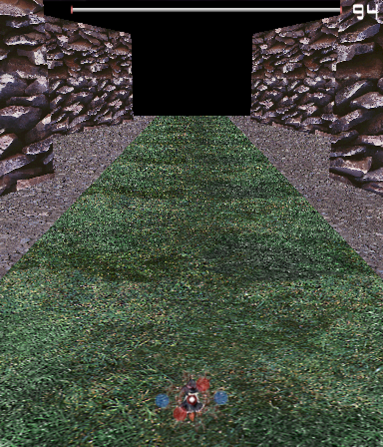
Note that I have set the elevation angle to 15 in order to better demonstrate the effect we have here, and it will remain that way for the rest of this script.
Here we create a pair of walls every 256 frames. Each wall calculates its length based on the rules we mentioned above. We're performing scaling here as well, with the 2:1 ratio being maintained. Note that we use ObjRender_SetZWrite() - this function sets things up so that newer walls don't render in front of older ones.
For this example, we use the Z coordinate to position the walls. We're initially positioning them 2048 units away in the Z direction, and they move closer to the camera with a specified movement speed. Note that the movement speed and spawn rate don't actually line up with the movement speed of the ground - getting the speeds just right is very difficult since we're using different methods for handling the 3D sprites.
Finally, we delete the objects after a certain amount of time has passed. The number used here is fairly arbitrary - it depends on how you use the camera.
Now, let's add the final touches to this stage background.
Our final step will consist of two parts: Side-sweep via Azimuth manipulation, and Perspective Clip modification.
First, side-sweeping. In the prior example, we change Azimuth over time. This time we will set the Azimuth based off of the sine of the counter. Note that we will use our initial value of -90 as our pivot point. I will use SetCameraAzimuthAngle(-90 + 20*sin(cameracount*0.5)) for now - feel free to change the values and see what works well.
Next, Perspective Clip. In this case, we will set the max to 4000, allowing us to see a bit farther. However, we will need to extend the background once more, and this also brings up another problem - the walls currently begin spawning at the start of the stage. It's preferable to have the player either enter the area or already be surrounded by walls. We will attempt the latter. For this, we will allow greater customization with the parameters provided to the walls.
task TNormalBackground() {
    let frameInvisible = 0;
    let cameracount = 0;
    let scrollspeed = 8;
    let walldistance = 256; // Distance from path

    let path1 = GetCurrentScriptDirectory ~ "img/u3l30sampleB1.png";
    let path2 = GetCurrentScriptDirectory ~ "img/u3l30sampleB2.png";

    let obj1 = ObjPrim_Create(OBJ_SPRITE_3D); // Flooring
    ObjRender_SetBlendType(obj1, BLEND_ALPHA);
    Obj_SetRenderPriority(obj1, 0.21);
    ObjPrim_SetTexture(obj1, path1);
    ObjSprite3D_SetDestRect(obj1, -1024, -1024 * 4, 1024, 1024 * 4); // Output ratio is 1x4
    ObjRender_SetAngleX(obj1, 90);

    let obj2 = ObjPrim_Create(OBJ_SPRITE_3D); // Path
    ObjRender_SetBlendType(obj2, BLEND_ALPHA);
    Obj_SetRenderPriority(obj2, 0.21);
    ObjPrim_SetTexture(obj2, path2);
    ObjSprite3D_SetDestRect(obj2, -128, -1024 * 4, 128, 1024 * 4); // Output ratio is 1x32
    ObjRender_SetAngleX(obj2, 90);

    ascent(i in 0..5) {
        CreateWall(-walldistance, -75, 2, 512 + i*512);
        CreateWall(walldistance, 75, 2, 512 + i*512);
        CreateWall(-walldistance, 75, 2, 256 + i*512);
        CreateWall(walldistance, -75, 2, 256 + i*512);
    }

    loop {
        if(bSpell) {
            frameInvisible++;
            if(frameInvisible >= 60) {
                Obj_SetVisible(obj1, false);
                Obj_SetVisible(obj2, false);
            }
        } else {
            frameInvisible = 0;
            Obj_SetVisible(obj1, true);
            Obj_SetVisible(obj2, true);
        }

        if (cameracount % 512 == 0) {
            CreateWall(-walldistance, -75, 2, 0);
            CreateWall(walldistance, 75, 2, 0);
        }
        if (cameracount % 512 == 256) {
            CreateWall(-walldistance, 75, 2, 0);
            CreateWall(walldistance, -75, 2, 0);
        }

        SetCameraAzimuthAngle(-90 + 20*sin(cameracount*0.5));

        // Scroll by setting the source rects
        ObjSprite3D_SetSourceRect(obj1, 0, 0 + cameracount*scrollspeed, 1024*8, 1024 * 32 + cameracount*scrollspeed);
        ObjSprite3D_SetSourceRect(obj2, 0, 0 + cameracount*scrollspeed, 1024  , 1024 * 32 + cameracount*scrollspeed);

        cameracount++;
        yield;
    }
}

task CreateWall(x, angle, movespeed, objcount) {
    let path3 = GetCurrentScriptDirectory ~ "img/u3l30sampleB3.png";

    let totallength = GetTotalWallLength(512, angle);

    let obj3 = ObjPrim_Create(OBJ_SPRITE_3D); // Wall
    ObjRender_SetBlendType(obj3, BLEND_ALPHA);
    Obj_SetRenderPriority(obj3, 0.21);
    ObjPrim_SetTexture(obj3, path3);
    ObjSprite3D_SetSourceRect(obj3, 0, 0, 1024*2, 1024);
    ObjSprite3D_SetDestRect(obj3, -totallength/2, 0, totallength/2, totallength/2);

    ObjRender_SetX(obj3, x);
    ObjRender_SetAngleY(obj3, angle);
    ObjRender_SetZWrite(obj3, true);

    loop {
        if(bSpell) {
            Obj_SetVisible(obj3, false);
        } else {
            Obj_SetVisible(obj3, true);
        }

        ObjRender_SetZ(obj3, 4096 - objcount*movespeed);

        if (objcount > 4096) {
            Obj_Delete(obj3);
        }

        objcount += 1;
        yield;
    }
}
As seen above, we've manipulated things to simulate walls spawning like usual, but with their counters pre-incremented.
With that, we've created our background. The complete script can be found here. Note that it suffers from a few rendering issues with render order.
Part 8: How do I utilize fog?
And finally, fog. If we were to apply fog with SetFogParam(), we spawn radial fog around the camera starting from the provided start parameter and moving outwards to the provided end parameter. Note that for our current background, this function will backfire spectacularly - this is because our floor is a single object. (NOTE: Fact check required)
In stages using meshes and a variety of objects, the built-in fog effect may indeed prove useful, and it may have some interesting uses...
Summary
- 3D sprites utilize the 3D camera and coordinate system
- Azimuth and Elevation angles control the camera position relative to the focus/focal point
- Yaw, Pitch, and Roll control the camera's rotation around its own axes
- 3D backgrounds can be generated using 3D sprites placed within the scene
- Depending on the Azimuth angle set, axes and rotations around axes such as those of Pitch and Roll may behave differently
Sources and External Resources
3D Camera images and content thanks to Drake on MotK. Source (Yaw/Pitch/Roll, Elevation/Azimuth)
I'd like to thank Dr. Misha Kazhdan for giving me enough experience with OpenGL to not puke when I was haphazardly experimenting with Danmakufu's camera during the production of this guide
I'd like to thank the creator of the Yukkuri for blessing me with the inspiration needed to decide that making a Yukkuri background was a good idea. Also, thanks to the Bullet Hell Engines server for showering me with enough Discord Nitro to actually write this thing to completion and draw the Yukkuris out of the recesses of my brain